No travel on this post. Just nerd stuff. 🙂
We’ve been mucking around with the refrigerator since the campervan was new. Coachmen didn’t vent the fridge properly and issued a service bulletin to correct the venting. My glorious dealer claimed to have fixed the issue. I discovered that not only did the dealer do a half-a$$ed fix, they also got reimbursed by the refrigerator manufacturer to replace a defective component – which they didn’t replace.
Shame on them.
In 2019 I redid the refrigerator venting, and in 2020 I re-insulated the area behind the fridge, installed fans to force-vent the fridge, and eventually replaced the refrigerator under warranty. The refrigerator now cools well under moderate temperatures without fans, and with the fans running will cool to 40F when the inside of the van is 100F.
Life is good.
But – running the fans at 100% all day or forgetting to turn them on in the morning is less than ideal, and the idea of manually switching fans on and off is old-fashioned. Seems to me that I should be able to measure the temperature in the area where the refrigerator vents and spin the fans only when needed & only as fast as needed. It would be nice if the system were able to tell me what it’s doing – how fast the fans are spinning, for example – and I also want the system to be fail-safe, so if my electronics stop working the fans will still run.
A project to correct this is in order.
There are lots of ways to accomplish this – the simplest being to either buy fans with built-in temperature sensors or add an inline temperature-based fan controller. These options don’t give me any data to measure how well they work, and simple is not the objective.
The un-simple way to accomplish this is with something that has a bit more smarts than a dumb fan controller. Like maybe a smart fan controller? I now have the excuse I needed to experiment with some new-to-me technology.
A Wemos D1 Mini ESP8266 microcontroller, a bit of C++ programming, a motor controller, relay, and soldering iron should suffice to meet my goals of controlling temperature and measuring results, while still providing a sufficient level of un-simplicity so as to not sully my reputation for over complicating pretty-much everything I touch.
Fans
I’ve been using ordinary PC computer fans for the existing setup (Arctic ‘P’ series, which provide a higher-than-normal static pressure). They run on 12 volts, are reasonably quiet, and don’t draw too much power, so are ideal for a campervan. They also can be variably-speeded (sp?) either by lowering the voltage or by switching on and off the 12v power with variable width pulses – a technique called pulse-width-modulation (PWM). The latter provides better control. I’m also somewhat familiar with pulse-width-modulation – my last PWM project being a mere forty-five years ago when I soldered together a PWM power supply to provide realistic speed control, acceleration, deceleration, and simulated momentum for my model train engines.
Time for a PWM refresher.
Measurements – DHT11 Temperature/Humidity Sensor
For my battery monitoring project I used a Raspberry PI. It works. For my battery heating project I used a DS18B20 temperature probe connected to the Pi. It works. I found out though, that there are other temperature sensors (DHT11 & DHT22) that work well with microcontrollers, use less power, and are easier to read. So I bought a few cheap Chinese knockoffs of a cheap Chinese DHT11, itself a clone of something that probably was invented in the US a few decades ago.
Smarts – Wemos Mini D1 Clone
To provide enough smarts to measure, control and report results I chose a cheap Chinese knockoff of a cheap Chinese ESP8266 based microcontroller, the Wemos Mini D1. The choice is partially because I have no idea what I’m doing, but mostly because a You-Tuber that I follow (Jason @ Everlanders) uses them to automate and control stuff in his camper, and he knows what he is doing.
The D1 Mini clone combines an ESP8266 processor, a tiny bit of flash (4MB, 1MB of which is useable for your program), a USB serial port, Wi-Fi, a handful of digital I/O pins and a very primitive operating system. There’s not much else to them. No keyboard, no monitor, no user interface. Software written in compiled C++ & loaded by re-flashing the device or scripts written in either Lua or Python, also loaded by re-flashing. I chose to use C++, giving me the opportunity to brush up on another skill I haven’t used in decades.
The nice part about the ESP environment is that some smarter-than-me volunteers extended the Arduino environment to support the ESP microcontrollers, so one can generally write code for the Arduino environment (where there are lots of libraries, tutorials, and example programs) and compile it to run on ESP’s. The Wemos and its clones also have built-in Wi-Fi, so I can cloud-enable them fairly easily.
Motor Control – Adfruit DRV8871
I chose an Adafruit DRV8871 motor controller. The 8871 will accept a PWM input from the microcontroller and pulse the 12V power to the fans. I also am using a 12V relay in line with the fans, controlled by the D1 Mini, and wired so that if the D1 Mini fails for any reason the relay will disconnect the D1 Mini microcontroller and power the fans with unmodulated 12V, spinning them at 100%.
I also wired the 12V power using common connectors, so that if I want to bypass both the microcontroller and relay, I can unplug the fans from the circuitry and re-plug the fans directly to 12V power.
You can tell that I have confidence in my engineering skills.
Monitoring
In my other projects, I use the Blynk IoT Cloud service and smartphone app to provide real-time access to the data from the batteries and temperature sensors. Ditto for this project. To use Blynk, one can either leverage their libraries – available for many different platforms – or make API calls. The Raspberry Pi based projects were using the API, but since I switched over to using an MQTT message bus (yes, my camper has a message bus – a topic for a future post, perhaps) I’m using the official Blynk Python libraries.
For this project I’m using the official C++ Blynk ESP8266 library.
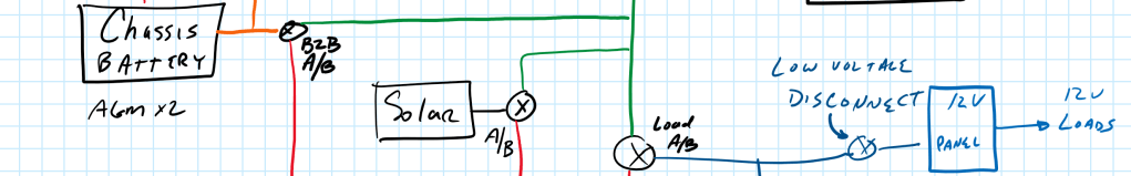
Power
The D1 Mini runs off 3.3V but has a 5V power input. The campervan is 12V. If you happen to accidently touch 12 volts to any of the D1 Mini pins, the D1 goes on strike and refuses to work. Permanently. As in forever. Good thing no-name clone D1’s are only a few bucks, come in packs of three, five or ten, and show in a day via Amazon Prime.
I’m using a L7805CV voltage regulator to drop the voltage from 12V to 5V. Another Chinese knockoff of something that originated in the US decades ago.
Mockup
The program logic is pretty simple. Connect to Wi-Fi, connect to Blynk, and start a few timers. The timers fire every half-minute, read the DHT11 temperature sensor, adjust the fan speed by changing the width of the PWM pulse., They then upload a few bits of data to the Blynk cloud. In keeping with the fail-safe schema, the software will keep measuring and adjusting even if there is no Wi-Fi or Blynk. The software will re-connect to both when they become available. In theory. Maybe. Fingers crossed.

After a bit of testing, I added a few features. Because the only way to change the software is to re-flash – a process that can fail and leave you with another D1 Mini that quits showing up for work – I added a few bits that allow me to on-the-fly change the temperature upper and lower limits, the fan lower RPM limit, and provide for a fan speed override. Without those features, I’d have to re-flash just to tweak the fan-speed-to-temperature ratio. Now I can push buttons on my phone.
After a bit more testing, I added a feature that reads the ambient temperature in the campervan cabin (something which I already have in the Raspberry Pi apps) and uses that measurement to adjust the upper and lower temperature thresholds. Without that feature the fans would run at 100% trying to cool the fridge coils to a temperature lower than the air being drawn across the coils. That’ll never work – at least not in this universe with our current laws of thermodynamics – so no sense in trying.
I also added a command-line interface that reads a ‘?’ command typed from my smartphone and dumps out current status.
‘Cause why not.
Pictures
Here’s what it looks like.


Summary
The fans now run faster when it’s hotter, slower when it’s cooler, and not at all when the coil temps are near the cabin air temperature. The setup has survived power outages, busted Wi-Fi, and went nearly a week without going up in smoke. I’m now able to adjust the parameters on the fly, so it was pretty easy to come up with a set that keeps the fan running at very low or not at all speeds during moderate weather and keeps the coils reasonably cool in hot temperatures, with the fans running no more than 50%.
Successful (so far).
I warned you that this was a nerd post. If you’ve read this far, you are either:
- A nerd.
- A nerd-sympathizer.
- Desparate for a solution to keep your refrigerator coils cool.
- COVID-quarantined, and really, really bored.
Or all of the above. 😁

Leave a comment